66 Results
View results:
Sort by:

To evaluate whether it is also necessary to consider the second-order analysis in a dynamic calculation, the sensitivity coefficient of interstory drift θ is provided in EN 1998‑1, Sections 2.2.2 and 4.4.2.2. It can be calculated and analyzed using RFEM 6 and RSTAB 9.
The coefficient θ is calculated as follows:$$\mathrm\theta\;=\;\frac{\displaystyle{\mathrm P}_\mathrm{tot}\;\cdot\;{\mathrm d}_\mathrm r}{{\mathrm V}_\mathrm{tot}\;\cdot\;\mathrm h}\;$$
The coefficient θ is calculated as follows:$$\mathrm\theta\;=\;\frac{\displaystyle{\mathrm P}_\mathrm{tot}\;\cdot\;{\mathrm d}_\mathrm r}{{\mathrm V}_\mathrm{tot}\;\cdot\;\mathrm h}\;$$

In order to be able to carry out a pushover analysis, it is necessary to transform the determined capacity curve into a simplified form. The N2 method is described in Eurocode EN 1998. This article should help to explain what a bilinearization according to the N2 method involves.

Both the determination of natural vibrations and the response spectrum analysis are always performed on a linear system. If nonlinearities exist in the system, they are linearized and thus not taken into account. They are caused by, for example, tension members, nonlinear supports, or nonlinear hinges. This article shows how you can handle them in a dynamic analysis.

For the stability verification of members using the equivalent member method, it is necessary to define effective or lateral-torsional buckling lengths in order to determine a critical load for stability failure. In this article an RFEM 6-specific function is presented, by which you can assign an eccentricity to the nodal supports and thus influence the determination of the critical bending moment considered in the stability analysis.

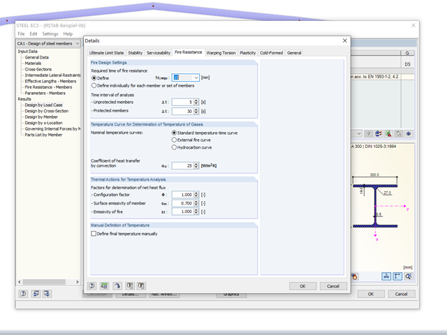
With the Steel Design add-on, you can design structural steel components in the event of fire using the simple design methods according to Eurocode 3. The component temperature at the time of the design check can be determined automatically according to the temperature-time curves specified in the standard. In addition to considering a cladding for fire protection, it is also possible for you to take account of the beneficial properties of hot-dip galvanization.

This article will show you a practical example of how to determine critical load factors and corresponding mode shapes in RFEM 6.

Given that realistic determination of the soil conditions significantly influences the quality of the structural analysis of buildings, the Geotechnical Analysis add-on is offered in RFEM 6 to determine the soil body to be analyzed.
The way to provide data obtained from field tests in the add-on and use the properties from soil samples to determine the soil massifs of interest was discussed in Knowledge Base article “Creation of the Soil Body from Soil Samples in RFEM 6”. This article, on the other hand, will discuss the procedure to calculate settlements and soil pressures for a reinforced concrete building.

You can use the stand-alone program RSECTION to determine the section properties for any thin-walled and massive cross-sections, as well as to perform a stress analysis. The previous Knowledge Base article titled "Graphical/Tabular Creation of User-defined Cross-sections in RSECTION 1" discussed the basis of defining cross-sections in the program. This article, on the other hand, is a summary of how to determine the section properties and perform a stress analysis.

Steel has poor thermal properties in terms of fire resistance. The thermal expansion for increasing temperature is very high compared to that of other building materials, and might result in effects that were not present in the design at normal temperature due to restraint in the component.As temperature increases, steel ductility increases, whereas its strength decreases. Since steel loses 50% of its strength at temperature of 600 °C, it is important to protect components against fire effects. In the case of protected steel components, the fire resistance duration can be increased due to the improved heating behavior.

In RFEM, it is possible to display the resultant of a section or release. This article explains which part of the sectional area is affected. The easiest way would be to refer the resultant to a cut face of the surface. However, since a section may run through several surfaces with different local coordinate systems, determination by means of a cut face is not possible.

A member's boundary conditions decisively influence the elastic critical moment for lateral-torsional buckling Mcr. The program uses a planar model with four degrees of freedom for its determination. The corresponding coefficients kz and kw can be defined individually for standard-compliant cross-sections. This allows you to describe the degrees of freedom available at both member ends due to the support conditions.

The reinforced concrete design for fire situations is carried out according to the simplified method based on EN 1992-1-2, Clause 4.2. The "zone method" described in Annex B.2 is used: The cross-section is subdivided into a number of parallel zones of equal thickness, and their temperature-dependent compressive strength is determined. The reduced load-bearing capacity in the event of fire exposure is thus represented by a reduced structural component's cross-section with reduced strengths.

The "4.0 Results - Summary" table displays the infinity norm at the end of the load case results. The norm is used to estimate the largest eigenvalue of a structure. The largest eigenvalue of a structure is estimated by numerical analysis, as accurate determination can be very time-consuming.

This article deals with the determination of the concrete reinforcement for a beam stressed by tension only according to EN 1992-1-1. The aim is to show the tensile load of a member-type element (without imposed deformations) and to define the concrete reinforcement in accordance with the standard's construction rules and provisions using the RFEM structural analysis software.
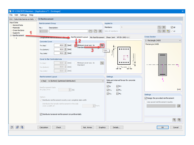
This article deals with the protection of reinforcement against corrosion defined according to EN 1992-1-1, also called concrete cover. The purpose of this article is to show how very many parameters defined in the Eurocodes for concrete reinforcements are considered in the RFEM structural analysis software.
Structures react differently to wind action depending on stiffness, mass, and damping. A basic distinction is made between buildings that are prone to vibration and those that are not.
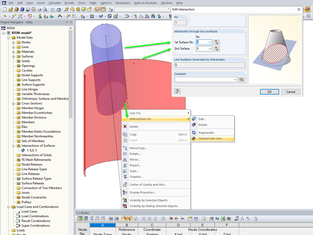
If you want to model two intersecting surfaces, RFEM offers you the possibility to create the section line automatically. In the program, this function is referred to as intersection. When generating an intersection, the modeled surface is split into components. This has the advantage that the components can be taken into account in the determination of the internal forces, or deactivated.
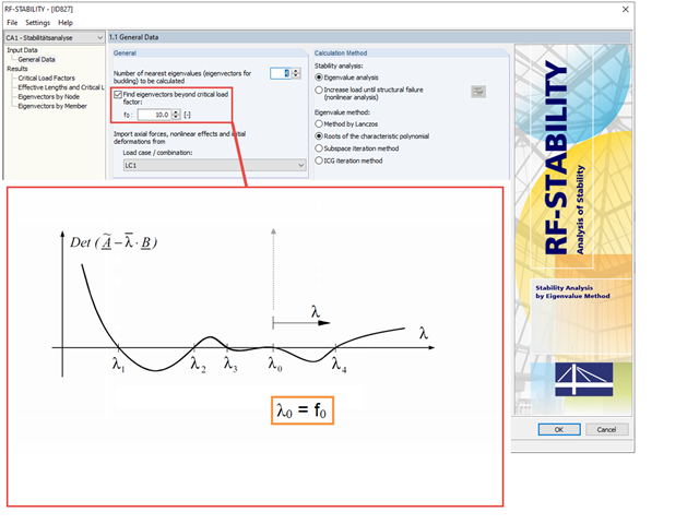
The function, which is also known as shifting, allows you to calculate critical load factors beyond a user‑defined initial value. Determination of the critical load factors is usually done from the smallest to the greatest critical load factor.

The classification of cross-sections according to EN 1993-1-1 using Table 5.2 is a simple method for designing the local buckling of cross-section parts. For cross-sections of cross-section class 4, it is then necessary to determine the effective cross-section properties according to EN 1993-1-5 in order to consider the influence of local buckling in the ultimate limit state designs.
The RF-/STEEL EC3 add‑on module allows for the fire protection design of structural steel components. The simplified analysis is performed by determining the steel temperature iteratively for a particular point of time.
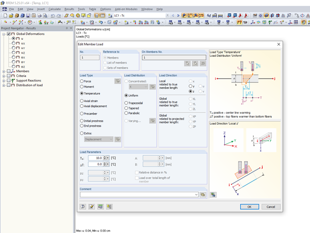
The RFEM and RSTAB structural analysis programs are able to simulate a thermal strain of structural components by means of temperature loads.
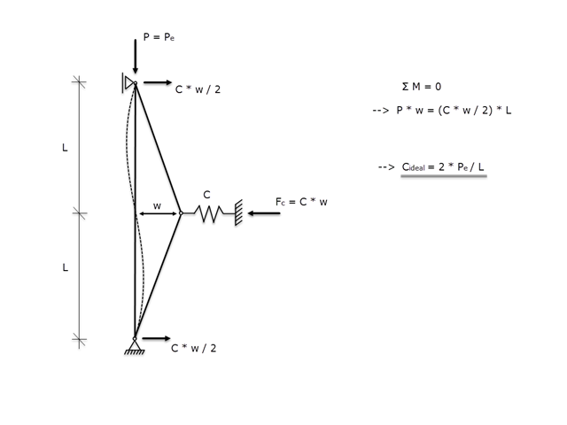
If a member is supported laterally to prevent buckling due to a compressive axial force, it must be ensured that the lateral support is actually able to prevent buckling. Therefore, the aim of this article is to determine the ideal spring stiffness of a lateral support using the Winter model.
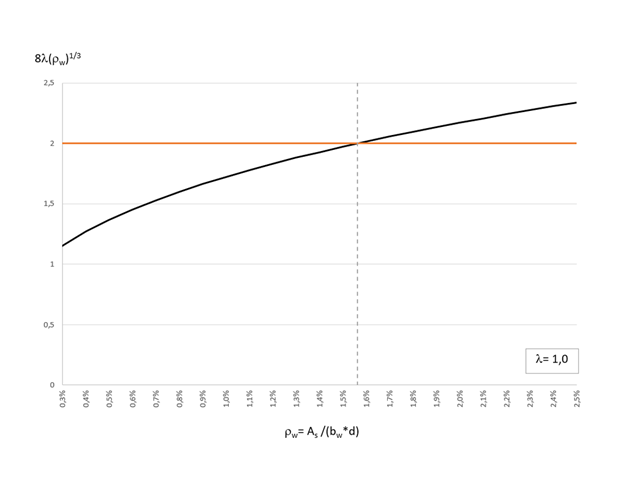
The most recent standard ACI 318‑19 redefines the long-term relation for the determination of the concrete shear resistance Vc. With the new method, the member height, the longitudinal reinforcement ratio, and the normal stress now influence the shear strength, Vc. This article describes the shear design updates, and the application is demonstrated using an example.

The European standard EN 1993-1-8, Section 4.5.3.3. provides the user with a simplified method for the ultimate limit state design of fillet welds. According to the standard, the design is fulfilled if the design value of the resultant acting on the fillet weld area is smaller than the design value of the weld's load-bearing capacity. Thus, if you want to dimension the weld for a surface model, you will be faced with a variety of results due to the nature of FEM calculations. Therefore, we show in the following text how to determine the force components from the model.

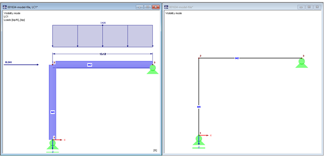
This technical article analyzes the effects of the connection stiffness on the determination of internal forces, as well as the design of connections using the example of a two-story, double-spanned steel frame.

The article titled Lateral-Torsional Buckling in Timber Construction | Theory explains the theoretical background for the analytical determination of the critical bending moment Mcrit or the critical bending stress σcrit for the lateral buckling of a bending beam. This article uses examples to verify the analytical solution with the result from the eigenvalue analysis.

Both the determination of natural vibrations and the response spectrum analysis are always performed on a linear system. If nonlinearities exist in the system, they are linearized and thus not taken into account. Straight tension members are very often used in practice. This article will show how you can display them approximately correctly in a dynamic analysis.
The beam is resting on the column, and the beam ends at the outer edge of the column. These requirements can be fulfilled easily in an architectural model with solids. In member analysis, simplified line models are used in which center lines meet in a common node. In this article, the influence of member eccentricities on the determination of internal forces is shown on three simple models.

With RF-/STEEL EC3, you can utilize nominal temperature-time curves in RFEM and RSTAB. The standard time-temperature curve (ETK), the external fire curve and the hydrocarbon fire curve are implemented. Moreover, the program provides the option to directly specify the final temperature of steel.
.png?mw=640&hash=6e011ea537587ceb48d9e642d642150a151c551e)
The ASCE 7-16 standard requires both balanced and unbalanced snow load case scenarios for a structure's design consideration. While this may be more intuitive for flat or even gable/hip type roofs, the determination of snow loads is increasingly difficult for arch roofs due to complex geometry. However, with guidance from ASCE 7-16 on snow load calculations for curved roofs and RFEM's efficient load application tools, it is possible to consider both balanced and unbalanced snow loads for a reliable and safe structure design.